别以为真懂Openstack: 虚拟机创建的50个步骤和100个知识点
2016年08月14日 20:33:47 peach_li 阅读数:12256
转载自:http://blog.itpub.net/18796236/viewspace-1840119/

别以为真懂Openstack!先别着急骂我,我也没有说我真懂Openstack
我其实很想弄懂Openstack,然而从哪里下手呢?作为程序员,第一个想法当然是代码,Code Talks,什么都可以忽悠,代码是实实在在的,何况原来也深入读过Lucene, Hadoop的源代码,总以为从代码下手,背后的原理变了然了。
说干就干,我喜欢读取代码的方式是按照情景阅读,比如在Lucene中跟踪索引的过程,跟踪搜索的过程,比如在Hadoop中,跟踪写入文件的过程,跟踪Map-Reduce的过程,于是在Openstack中决定跟踪虚拟机创建的整个过程
好在很多先贤已经做过这方面的事情,想来也没有那么的困难。
比较推荐一篇 Request Flow for Provisioning Instance in Openstack(http://ilearnstack.com/2013/04/26/request-flow-for-provisioning-instance-in-openstack/),如果被墙挡住了,我转到了[转]Request Flow for Provisioning Instance in Openstack

然而真的开始了这个旅程,却发现Openstack中涉及的知识绝非只有python代码,而必须有大量的外围知识方可理解。
Openstack社区强大,各门各派武林高手竞相亮招,不断的贡献各种各样的插件,模块:
模块繁多:除了Iaas平台的基本组件keystone, nova, glance, neutron, cinder之外,很多人都想在Openstack里面创建新的模块,如雨后春笋冒了出来,Telemetry (Ceilometer), Orchestration (Heat), Database Service (Trove), Data processing (Sahara), Bare metal (Ironic), Queue service (Marconi), Key management (Barbican), DNS Services (Designate), Deployment (TripleO),哦,太多了,研究不过来,好吧,先收缩一下雄心壮志,专注IaaS层吧,所以有关这些模块的知识点,本文没有涉及。
插件繁多:除了Openstack支持的一些开源插件外,各大厂商都争先恐后的开发自己的插件,似乎害怕被Openstack社区拒之门外。我没有钱去买去试这么多厂家的设备和插件,所以只能使用开源免费默认的KVM,LVM,Openvswitch等,所以有关各种厂商的插件的知识点,本文没有涉及。

好了,我已经退缩到不能再退缩的scope了,下面就进入Openstack的虚拟机创建之旅。
我学习知识采用贪心算法,遇到在哪个步骤先遇到某个知识点就研究,可能这个知识点在其他的模块也有应用,到时候就发现这个知识点已经被遍历过了,当然也没有太过贪心,遇到过于繁复,过于生僻的,也当机立断,进行剪枝。
一、Keystone

步骤1: 任何客户端想要访问任何服务,都需要先从keystone拿到Token
还记得原来那个短短的UUID的Token么?例如"aef56cc3d1c9192b0257fba1a420fc37"
后来变成了一长串不知道是什么的东东:
MIIDsAYJKoZIhvcNAQcCoIIDoTCCA50CAQExCTAHBgUrDgMCGjCCAokGCSqGSIb3DQEHAaCCAnoEggJ2ew0KICAgICJhY2Nlc3MiOiB7DQogICAgICAgICJtZXRhZGF0YSI6IHsNCiAgICAgICAgICAgIC4uLi5tZXRhZGF0YSBnb2VzIGhlcmUuLi4uDQogICAgICAgIH0sDQogICAgICAgICJzZXJ2aWNlQ2F0YWxvZyI6IFsNCiAgICAgICAgICAgIC4uLi5lbmRwb2ludHMgZ29lcyBoZXJlLi4uLg0KICAgICAgICBdLA0KICAgICAgICAidG9rZW4iOiB7DQogICAgICAgICAgICAiZXhwaXJlcyI6ICIyMDEzLTA1LTI2VDA4OjUyOjUzWiIsDQogICAgICAgICAgICAiaWQiOiAicGxhY2Vob2xkZXIiLA0KICAgICAgICAgICAgImlzc3VlZF9hdCI6ICIyMDEzLTA1LTI1VDE4OjU5OjMzLjg0MTgxMSIsDQogICAgICAgICAgICAidGVuYW50Ijogew0KICAgICAgICAgICAgICAgICJkZXNjcmlwdGlvbiI6IG51bGwsDQogICAgICAgICAgICAgICAgImVuYWJsZWQiOiB0cnVlLA0KICAgICAgICAgICAgICAgICJpZCI6ICI5MjVjMjNlYWZlMWI0NzYzOTMzZTA4YTRjNDE0M2YwOCIsDQogICAgICAgICAgICAgICAgIm5hbWUiOiAidXNlciINCiAgICAgICAgICAgIH0NCiAgICAgICAgfSwNCiAgICAgICAgInVzZXIiOiB7DQogICAgICAgICAgICAuLi4udXNlcmRhdGEgZ29lcyBoZXJlLi4uLg0KICAgICAgICB9DQogICAgfQ0KfQ0KMYH/MIH8AgEBMFwwVzELMAkGA1UEBhMCVVMxDjAMBgNVBAgTBVVuc2V0MQ4wDAYDVQQHEwVVbnNldDEOMAwGA1UEChMFVW5zZXQxGDAWBgNVBAMTD3d3dy5leGFtcGxlLmNvbQIBATAHBgUrDgMCGjANBgkqhkiG9w0BAQEFAASBgEh2P5cHMwelQyzB4dZ0FAjtp5ep4Id1RRs7oiD1lYrkahJwfuakBK7OGTwx26C+0IPPAGLEnin9Bx5Vm4cst/0+COTEh6qZfJFCLUDj5b4EF7r0iosFscpnfCuc8jGMobyfApz/dZqJnsk4lt1ahlNTpXQeVFxNK/ydKL+tzEjg
这里面是什么,不可能是一般的乱码吧。
于是看到了这篇文章
Understanding OpenStack Authentication: Keystone PKI (https://www.mirantis.com/blog/understanding-openstack-authentication-keystone-pki/)
[转]Understanding OpenStack Authentication: Keystone PKI
才了解了这个过程
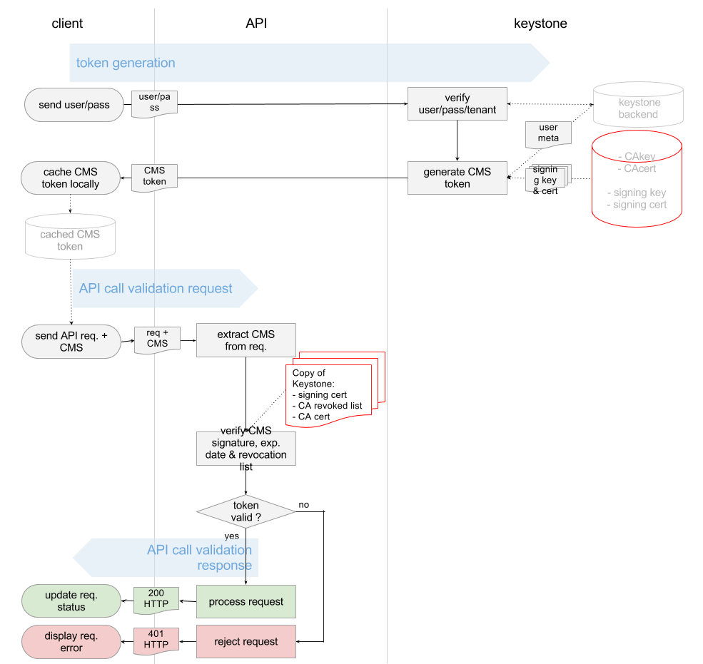
看懂这个图,如果没有点信息安全课程的底子,还真不行。什么各种CA, Certificate, Key,直接就晕了。
于是看了《Principles of Information Security,4ed》的第八章Cryptography,以及《Information Security Principle and Practice》才有所了悟。
下面这篇博客也对相关的概念作了形象的描述
数字证书原理(http://blog.sina.com.cn/s/blog_44ee37cd01016r1h.html)
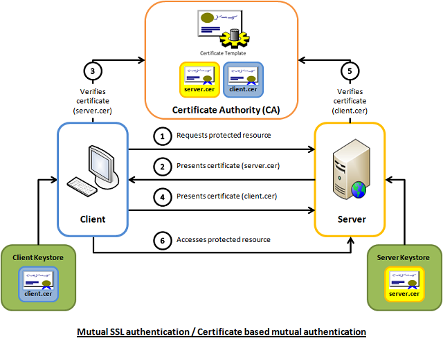
这些概念都是了解SSL和https的必须的,而且我们在部署Openstack的时候,所有的服务最好也部署成HTTPS的。
下面这两篇文章会帮你更好的了解SSL
http://httpd.apache.org/docs/2.2/ssl/ssl_intro.html
http://www.codeproject.com/Articles/326574/An-Introduction-to-Mutual-SSL-Authentication
要使用SSL,两个必备的工具Openssl和certtool,其中Openssl比较常用,而certtool是用于配置libvirt远程连接的官方推荐的工具。
对于Openssl,推荐下面的链接
http://pages.cs.wisc.edu/~zmiller/ca-howto/如果被墙屏蔽了可以访问How To Setup a CA
对于certtool,推荐libvirt的官方文档,讲的非常的形象具体
http://wiki.libvirt.org/page/TLSSetup
keystone除了authentication的功能,还有authorization。
对于访问控制Access Control,发现有多种http://en.wikipedia.org/wiki/Access_control,而Openstack采用的是Role Based Access Control RBAC。
其中在V2中采用的每个Service下面的policy.json文件,访问控制是每个Service自己决策的。后来在V3中,除了policy.json文件,还可以将Policy在数据库中创建,实现了keystone的统一管理。
推荐下面的文章
Customizing OpenStack RBAC policies
[转] Customizing OpenStack RBAC policies
Mandatory Access Control (MAC)在Openstack中也有应用,就是对Libvirt对Host文件的访问控制AppArmor。当你使用virsh命令进行操作的时候,如果发现自己是root,但是还没有权限,八成就是它的原因了。
推荐http://ubuntuforums.org/showthread.php?t=1008906
用户管理也是Keystone的一大工作
在V2中,结构比较简单,用一个三角形就可以明白

Keystone V3中的概念就比较多了,也相对复杂,文档较少,比较推荐下面的文章。
http://www.florentflament.com/blog/setting-keystone-v3-domains.html
[转]Setting Keystone v3 domains
我也画了一幅图,来帮助理解这个过程。

二、nova-api

步骤3:nova-api接收请求
nova-api接收请求,也不是随便怎么来都接收的,而是需要设定rate limits,默认的实现是在ratelimit的middleware里面实现的。
然而有时候,我们希望实现distributed rate-limiting,从而Turnstile是一个不错的选择。
https://github.com/klmitch/turnstile
http://pypi.python.org/pypi/turnstile
步骤4:对Token的验证
步骤5:查看Policy
这两步已经在keystone的时候研究过
步骤6:检查quota
nova, neutron, Cinder各有各的quota,并且可以从命令行进行管理
# nova -h | grep quota
quota-class-show List the quotas for a quota class.
quota-class-update Update the quotas for a quota class.
quota-defaults List the default quotas for a tenant.
quota-delete Delete quota for a tenant/user so their quota will
quota-show List the quotas for a tenant/user.
quota-update Update the quotas for a tenant/user.
# nova quota-show
+-----------------------------+-------+
| Quota | Limit |
+-----------------------------+-------+
| instances | 10 |
| cores | 20 |
| ram | 51200 |
| floating_ips | 10 |
| fixed_ips | -1 |
| metadata_items | 128 |
| injected_files | 5 |
| injected_file_content_bytes | 10240 |
| injected_file_path_bytes | 255 |
| key_pairs | 100 |
| security_groups | 10 |
| security_group_rules | 20 |
+-----------------------------+-------+
# cinder -h | grep quota
quota-class-show List the quotas for a quota class.
quota-class-update Update the quotas for a quota class.
quota-defaults List the default quotas for a tenant.
quota-show List the quotas for a tenant.
quota-update Update the quotas for a tenant.
quota-usage List the quota usage for a tenant.
# cinder quota-show 1779b3bc725b44b98726fb0cbdc617b1
+-----------+-------+
| Property | Value |
+-----------+-------+
| gigabytes | 1000 |
| snapshots | 10 |
| volumes | 10 |
+-----------+-------+
# neutron -h | grep quota
quota-delete Delete defined quotas of a given tenant.
quota-list List quotas of all tenants who have non-default quota values.
quota-show Show quotas of a given tenant
quota-update Define tenant's quotas not to use defaults.
# neutron quota-show 1779b3bc725b44b98726fb0cbdc617b1
+---------------------+-------+
| Field | Value |
+---------------------+-------+
| floatingip | 50 |
| network | 10 |
| port | 50 |
| router | 10 |
| security_group | 10 |
| security_group_rule | 100 |
| subnet | 10 |
+---------------------+-------+
推荐下面的文章
openstack nova 基础知识——Quota(配额管理)
http://www.sebastien-han.fr/blog/2012/09/19/openstack-play-with-quota/
步骤7:在数据库中创建Instance实例
有关nova的database schema参考下面的文章
http://www.prestonlee.com/2012/05/03/openstack-nova-essex-mysql-database-schema-diagram-and-sql/
MySQL是Openstack中最重要的组件之一,所以在生产环境中High Availability是必须的。
MySQL的HA有下面几种方式:
http://dev.mysql.com/doc/mysql-ha-scalability/en/index.html
| Requirement | MySQL Replication | MySQL with DRBD with Corosync and Pacemaker | MySQL Cluster |
| Availability | |||
| Platform Support | All Supported by MySQL Server | Linux | All Supported by MySQL Cluster |
| Automated IP Failover | No | Yes | Depends on Connector and Configuration |
| Automated Database Failover | No | Yes | Yes |
| Automatic Data Resynchronization | No | Yes | Yes |
| Typical Failover Time | User / Script Dependent | Configuration Dependent, 60 seconds and Above | 1 Second and Less |
| Synchronous Replication | No, Asynchronous and Semisynchronous | Yes | Yes |
| Shared Storage | No, Distributed | No, Distributed | No, Distributed |
| Geographic redundancy support | Yes | Yes, via MySQL Replication | Yes, via MySQL Replication |
| Update Schema On-Line | No | No | Yes |
| Scalability | |||
| Number of Nodes | One Master, Multiple Slaves | One Active (primary), one Passive (secondary) Node | 255 |
| Built-in Load Balancing | Reads, via MySQL Replication | Reads, via MySQL Replication | Yes, Reads and Writes |
| Supports Read-Intensive Workloads | Yes | Yes | Yes |
| Supports Write-Intensive Workloads | Yes, via Application-Level Sharding | Yes, via Application-Level Sharding to Multiple Active/Passive Pairs | Yes, via Auto-Sharding |
| Scale On-Line (add nodes, repartition, etc.) | No | No | Yes |
要想系统的学习Mysql replication,推荐下面的这本书
《MySQL High Availability Tools for Building Robust Data Centers》
还有一种方式是Mysql + galera,可以搭建Active + Active的Mysql应用

参考下面的两篇文章
http://www.sebastien-han.fr/blog/2012/04/08/mysql-galera-cluster-with-haproxy/
http://www.sebastien-han.fr/blog/2012/04/01/mysql-multi-master-replication-with-galera/
还有一种常见的HA的技术,就是pacemaker

最底层是通信层corosync/openais
负责cluster中node之间的通信
上一层是Resource Allocation Layer,包含下面的组件:
CRM Cluster Resouce Manager
是总管,对于resource做的任何操作都是通过它。每个机器上都有一个CRM。
CIB Cluster Information Base
CIB由CRM管理,是在内存中的XML数据库,保存了cluster的配置和状态。我们查询出来的configuration都是保存在CIB里面的。nodes, resources, constraints, relationship.
DC Designated Coordinator
每个node都有CRM,会有一个被选为DC,是整个Cluster的大脑,这个DC控制的CIB是master CIB,其他的CIB都是副本。
PE Policy Engine
当DC需要进行一些全局配置的时候,首先由PE根据当前的状态和配置,计算出将来的状态,并生成一系列的action,使得cluster从初始状态变为结果状态。PE仅仅在DC上运行。
LRM Local Resource Manager
本地的resource管理,调用resource agent完成操作,启停resource,将结果返回给CRM
再上一层是Resource Layer
包含多个resource agent。resource agent往往是一些shell script,用来启动,停止,监控resource的状态。
要弄懂Pacemaker,推荐读《SUSE high availability guide》
https://www.suse.com/documentation/sle_ha/singlehtml/book_sleha/book_sleha.html
本人做了一些笔记和实验,请参考
步骤8:创建filter_properties,用于nova scheduler
步骤9:发送RPC给nova-conductor
有关nova-conductor的文章
http://cloudystuffhappens.blogspot.com/2013/04/understanding-nova-conductor-in.html
在Openstack中,RPC的发送是通过RabbitMQ
RabbitMQ可以通过Pacemaker进行HA,当然也可以搭建自己的RabbitMQ Cluster
学习RabbitMQ当然首推《RabbitMQ in Action》
本人也做了一些笔记
RabbitMQ in Action (1): Understanding messaging
RabbitMQ in Action (2): Running and administering Rabbit
RabbitMQ in Action(5): Clustering and dealing with failure
还没完全读完,敬请谅解
当然Openstack中对于RabbitMQ的使用,一篇很好的文章是
本人也对RPC的调用过程进行了代码分析
步骤10:nova-condutor创建request_spec,用于scheduler
步骤11:nova-conductor发送RPC给nova-scheduler
三、nova-scheduler

选择一个物理机来创建虚拟机,我们称为schedule的过程
nova scheduler的一个经典的图如下

就是先Filter再Weighting,其实scheduler的过程在很早就参与了。
步骤13:对Host进行Filtering
Filtering主要通过两个变量进行,request_spec和filter_properties,而这些变量在前面的步骤,都已经准备好了。
而不同的Filter只是利用这些信息,然后再根据从HostManager统计上来的HostState信息,选出匹配的Host。
request_spec中的第一个信息就是image的properties信息,尤其是当你想支持多种Hypervisor的时候,Xen的image, KVM的image, Hyper-V的image各不相同,如何保证image跑在正确的Hypervisor上?在image里面这种hypervisor_type property就很必要。
请阅读下面的文章
http://www.cloudbase.it/filtering-glance-images-for-hyper-v/
image properties还会有min_ram, min_disk,只有内存和硬盘够大才可以。
Flavor里面可以设置extra_specs,这是一系列key-value值,在数据结构中,以instance_type变量实现,可以在里面输入这个Flavor除了资源需求的其他参数,从而在Filter的时候,可以使用。
host aggregates将所有的Host分成多个Group,当然不同的Group可以根据不同的属性Metadata划分,一种是高性能和低性能。
在Openstack文档中,这个例子很好的展示了host aggregates和Flavor extra_specs的配合使用
http://docs.openstack.org/trunk/config-reference/content/section_compute-scheduler.html
Example: Specify compute hosts with SSDs
This example configures the Compute service to enable users to request nodes that have solid-state drives (SSDs). You create a fast-iohost aggregate in the nova availability zone and you add the ssd=true key-value pair to the aggregate. Then, you add the node1, and node2compute nodes to it.
$ nova aggregate-create fast-io nova
+----+---------+-------------------+-------+----------+
| Id | Name    | Availability Zone | Hosts | Metadata |
+----+---------+-------------------+-------+----------+
| 1  | fast-io | nova              |       |          |
+----+---------+-------------------+-------+----------+

$ nova aggregate-set-metadata 1 ssd=true
+----+---------+-------------------+-------+-------------------+
| Id | Name    | Availability Zone | Hosts | Metadata          |
+----+---------+-------------------+-------+-------------------+
| 1  | fast-io | nova              | []    | {u'ssd': u'true'} |
+----+---------+-------------------+-------+-------------------+

$ nova aggregate-add-host 1 node1
+----+---------+-------------------+-----------+-------------------+
| Id | Name    | Availability Zone | Hosts      | Metadata          |
+----+---------+-------------------+------------+-------------------+
| 1  | fast-io | nova              | [u'node1'] | {u'ssd': u'true'} |
+----+---------+-------------------+------------+-------------------+

$ nova aggregate-add-host 1 node2
+----+---------+-------------------+---------------------+-------------------+
| Id | Name    | Availability Zone | Hosts                | Metadata          |
+----+---------+-------------------+----------------------+-------------------+
| 1  | fast-io | nova              | [u'node1', u'node2'] | {u'ssd': u'true'} |
+----+---------+-------------------+----------------------+-------------------+
Use the nova flavor-create command to create the ssd.large flavor called with an ID of 6, 8 GB of RAM, 80 GB root disk, and four vCPUs.
$ nova flavor-create ssd.large 6 8192 80 4 +----+-----------+-----------+------+-----------+------+-------+-------------+-----------+-------------+
| ID | Name      | Memory_MB | Disk | Ephemeral | Swap | VCPUs | RXTX_Factor | Is_Public | extra_specs |
+----+-----------+-----------+------+-----------+------+-------+-------------+-----------+-------------+
| 6  | ssd.large | 8192      | 80   | 0         |      | 4     | 1           | True      | {}          |
+----+-----------+-----------+------+-----------+------+-------+-------------+-----------+-------------+
Once the flavor is created, specify one or more key-value pairs that match the key-value pairs on the host aggregates. In this case, that is the ssd=true key-value pair. Setting a key-value pair on a flavor is done using the nova flavor-key command.
$ nova flavor-key ssd.large set ssd=true
Once it is set, you should see the extra_specs property of the ssd.large flavor populated with a key of ssd and a corresponding value of true.
$ nova flavor-show ssd.large
+----------------------------+-------------------+
| Property                   | Value             |
+----------------------------+-------------------+
| OS-FLV-DISABLED:disabled   | False             |
| OS-FLV-EXT-DATA:ephemeral  | 0                 |
| disk                       | 80                |
| extra_specs                | {u'ssd': u'true'} |
| id                         | 6                 |
| name                       | ssd.large         |
| os-flavor-access:is_public | True              |
| ram                        | 8192              |
| rxtx_factor                | 1.0               |
| swap                       |                   |
| vcpus                      | 4                 |
+----------------------------+-------------------+
Now, when a user requests an instance with the ssd.large flavor, the scheduler only considers hosts with the ssd=true key-value pair. In this example, these are node1 and node2.
另一个作用是Xen和KVM的POOL分开,有利于XEN进行Live Migration
另一个作用是Windows和Linux的POOL分开,因为Windows是需要收费的,而Linux大多不需要,Windows的收费是按照物理机,而非虚拟机来收费的,所有需要尽量的将windows的虚拟机放到一个物理机上。
Filter_properties的里面scheduler_hints是一个json,里面可以设置任何值,用于Filter的时候使用。
例如JsonFilter
The JsonFilter allows a user to construct a custom filter by passing a scheduler hint in JSON format. The following operators are supported:
=
<
>
in
<=
>=
not
or
and
The filter supports the following variables:
$free_ram_mb
$free_disk_mb
$total_usable_ram_mb
$vcpus_total
$vcpus_used
Using the nova command-line tool, use the --hint flag:
$ nova boot --image 827d564a-e636-4fc4-a376-d36f7ebe1747 --flavor 1 --hint query='[">=","$free_ram_mb",1024]' server1
With the API, use the os:scheduler_hints key:
![]()
{
"server": {
"name": "server-1",
"imageRef": "cedef40a-ed67-4d10-800e-17455edce175",
"flavorRef": "1"
},
"os:scheduler_hints": {
"query": "[>=,$free_ram_mb,1024]"
}
}
我们可以指定某个物理机,用下面的命令--availability-zone <zone-name>:<host-name>
步骤14:对合适的Hosts进行weighting并且排序
选出了Hosts,接下来就是进行Weighting的操作
Weighting可以根据很多变量来,一般来说Memory和disk是最先需要满足的,CPU和network io则需要次要考虑,一般来说,对于付钱较少的Flavor,能满足memory和disk就可以了,对于付钱较多的Flavor,则需要保证其CPU和network io.
步骤15:nova-scheduler想选出的Host发送RPC
四、Nova-compute

步骤17:nova-compute接收到请求后,通过Resource Tracker将创建虚拟机所需要的资源声明占用
步骤18:调用Neutron API配置Network,虚拟机处于Networking的状态
需要注意的是,这一步虽然是配置Network,但是主要是数据结构的准备,真正的设备并没有创建。
由于在创建虚拟机的时候,我们指定了将虚拟机放到哪个private network里面,因而在创建真正的设备之前,所有的信息都需要准备好。
这里的知识点设计Network的创建,然而这一步其实在虚拟机创建之前就应该做好。
一个最简单的场景是通过下面的脚本创建网络
#!/bin/bash
TENANT_NAME="openstack"
TENANT_NETWORK_NAME="openstack-net"
TENANT_SUBNET_NAME="${TENANT_NETWORK_NAME}-subnet"
TENANT_ROUTER_NAME="openstack-router"
FIXED_RANGE="192.168.0.0/24"
NETWORK_GATEWAY="192.168.0.1"
PUBLIC_GATEWAY="172.24.1.1"
PUBLIC_RANGE="172.24.1.0/24"
PUBLIC_START="172.24.1.100"
PUBLIC_END="172.24.1.200"
TENANT_ID=$(keystone tenant-list | grep " $TENANT_NAME " | awk '{print $2}')
(1) TENANT_NET_ID=$(neutron net-create --tenant_id $TENANT_ID $TENANT_NETWORK_NAME --provider:network_type gre --provider:segmentation_id 1 | grep " id " | awk '{print $4}')
(2) TENANT_SUBNET_ID=$(neutron subnet-create --tenant_id $TENANT_ID --ip_version 4 --name $TENANT_SUBNET_NAME $TENANT_NET_ID $FIXED_RANGE --gateway $NETWORK_GATEWAY --dns_nameservers list=true 8.8.8.8 | grep " id " | awk '{print $4}')
(3) ROUTER_ID=$(neutron router-create --tenant_id $TENANT_ID $TENANT_ROUTER_NAME | grep " id " | awk '{print $4}')
(4) neutron router-interface-add $ROUTER_ID $TENANT_SUBNET_ID
(5) neutron net-create public --router:external=True
(6) neutron subnet-create --ip_version 4 --gateway $PUBLIC_GATEWAY public $PUBLIC_RANGE --allocation-pool start=$PUBLIC_START,end=$PUBLIC_END --disable-dhcp --name public-subnet
(7) neutron router-gateway-set ${TENANT_ROUTER_NAME} public

为这个Tenant创建一个private network,不同的private network是需要通过VLAN tagging进行隔离的,互相之间broadcast不能到达,这里我们用的是GRE模式,也需要一个类似VLAN ID的东西,称为Segment ID
创建一个private network的subnet,subnet才是真正配置IP网段的地方,对于私网,我们常常用192.168.0.0/24这个网段
为这个Tenant创建一个Router,才能够访问外网
将private network连接到Router上
创建一个External Network
创建一个Exernal Network的Subnet,这个外网逻辑上代表了我们数据中心的物理网络,通过这个物理网络,我们可以访问外网。因而PUBLIC_GATEWAY应该设为数据中心里面的Gateway, PUBLIC_RANGE也应该和数据中心的物理网络的CIDR一致,否则连不通,而之所以设置PUBLIC_START和PUBLIC_END,是因为在数据中心中,不可能所有的IP地址都给Openstack使用,另外可能搭建了VMware Vcenter,可能有物理机器,仅仅分配一个区间给Openstack来用。
将Router连接到External Network
经过这个流程,从虚拟网络,到物理网络就逻辑上联通了。
然而真正的创建底层的设备,却是通过具体的命令来的,本人总结了一下:
当然还有更复杂的场景,参考这篇文章
步骤19:生成MAC Address
步骤20: 获取DHCP Server的配置
步骤21:获取Network的信息
步骤22:获取Security Group的信息
步骤23:拿着所有的信息,创建Port对象,是一个Tap device,当然真正的设备还没有创建
步骤24:调用Libvirt Driver创建虚拟机
五、Image

在创建Instance之前,当然需要Image,Image后来发现是一个大学问。
在Openstack里面,对于KVM,应用到的Image格式主要是两种RAW和qcow2,
raw格式简单,容易转换为其他的格式。需要文件系统的支持才能支持sparse file,性能相对较高。
qcow2是动态的,相对于raw来说,有下列的好处:
即便文件系统不支持sparse file,文件大小也很小
Copy on write
Snapshot
压缩
加密
具体的格式和特点,参考下面的文章
QEMU KVM libvirt手册(4) – images
创建一个image,有多种方法
一种方法是通过virt-install,讲hard disk设为一个image文件, 从CDROM启动一个虚拟机,按照正常的安装流程来,最后操作系统安装好,image再经过qemu-img进行处理,压缩,最终形成image。
参考文章
当然现在有了更先进的方法,就是libguestfs,它可以轻松基于已有版本的image创建一个你想要的image,就是virt-builder
参考文章
当然一个可以在Openstack里面使用的image,绝不是仅仅安装一个操作系统那么简单。
在OpenStack Virtual Machine Image Guide中详细写了一个Linux Image的各种需求
Disk partitions and resize root partition on boot (cloud-init)
No hard-coded MAC address information
Ensure ssh server runs
Disable firewall
Access instance by using ssh public key (cloud-init)
Use cloud-init to fetch the public key
Process user data and other metadata (cloud-init)
Ensure image writes boot log to console
另外加几条:
包含MBR和bootloader,可以自启动
支持virtio的disk和network driver
使用DHCP分配IP
当一个Linux的Image安装完毕后,总要测试一下:
能通过key ssh上去吗
能够文件注入吗
cloud-init是否运行了
文件系统被resize为flavor大小了吗
hostname设为文件名吗
timezone设的对吗
/etc/fstab干净正确吗
虚拟机的log被正确输出了吗
/tmp路径下干净吗
能打snapshot吗
block storage添加后能正常看到和使用吗
对于windows image,却要复杂的多,windows真的不是对cloud友好的。
首先必须用virt-install将windows系统安装好。
windows要想使用virtio,就必须将windows版本的virtio安装好。即便安装好,还要在device manager里面update driver才好。
Remote Access要打开,要不怎么远程桌面啊。
安装一个SSH Server吧,有时候需要创建虚拟机后,自动执行脚本安装东西,不能通过远程桌面来。
安装windows版本的cloud-init cloudbase-init
别忘了运行windows update来更新windows,否则会有很多安全漏洞。
在device manager里面添加一个serial console的device
windows的硬盘占用通常很大,运行一下disk cleanup tool可以清空一些硬盘。
微软有一个SDelete工具,可以讲未分配的空间设为0,从而可以压缩硬盘。
别忘了License问题。
有时候windows配置网络的时候,会弹出对话框,这是家庭网络,工作网络,还是公共网络?这会使得网络配置死在哪里,在注册表里干掉他。
运行sysprep
对于cloud-init,参考下面的文章
http://cloudinit.readthedocs.org/en/latest/index.html
http://www.scalehorizontally.com/2013/02/24/introduction-to-cloud-init/
在ubuntu中,cloud-init主要包括
配置文件在/etc/cloud下面,默认的cloud.cfg如下
root@dfasdfsdafasdf:/etc/cloud# cat cloud.cfg
# The top level settings are used as module
# and system configuration.
# A set of users which may be applied and/or used by various modules
# when a 'default' entry is found it will reference the 'default_user'
# from the distro configuration specified below
users:
- default
# If this is set, 'root' will not be able to ssh in and they
# will get a message to login instead as the above $user (ubuntu)
disable_root: true
# This will cause the set+update hostname module to not operate (if true)
preserve_hostname: false
# Example datasource config
# datasource:
# Ec2:
# metadata_urls: [ 'blah.com' ]
# timeout: 5 # (defaults to 50 seconds)
# max_wait: 10 # (defaults to 120 seconds)
# The modules that run in the 'init' stage
cloud_init_modules:
- migrator
- seed_random
- bootcmd
- write-files
- growpart
- resizefs
- set_hostname
- update_hostname
- update_etc_hosts
- ca-certs
- rsyslog
- users-groups
- ssh
# The modules that run in the 'config' stage
cloud_config_modules:
# Emit the cloud config ready event
# this can be used by upstart jobs for 'start on cloud-config'.
- emit_upstart
- disk_setup
- mounts
- ssh-import-id
- locale
- set-passwords
- grub-dpkg
- apt-pipelining
- apt-configure
- package-update-upgrade-install
- landscape
- timezone
- puppet
- chef
- salt-minion
- mcollective
- disable-ec2-metadata
- runcmd
- byobu
# The modules that run in the 'final' stage
cloud_final_modules:
- rightscale_userdata
- scripts-vendor
- scripts-per-once
- scripts-per-boot
- scripts-per-instance
- scripts-user
- ssh-authkey-fingerprints
- keys-to-console
- phone-home
- final-message
- power-state-change
# System and/or distro specific settings
# (not accessible to handlers/transforms)
system_info:
# This will affect which distro class gets used
distro: ubuntu
# Default user name + that default users groups (if added/used)
default_user:
name: ubuntu
lock_passwd: True
gecos: Ubuntu
groups: [adm, audio, cdrom, dialout, dip, floppy, netdev, plugdev, sudo, video]
sudo: ["ALL=(ALL) NOPASSWD:ALL"]
shell: /bin/bash
# Other config here will be given to the distro class and/or path classes
paths:
cloud_dir: /var/lib/cloud/
templates_dir: /etc/cloud/templates/
upstart_dir: /etc/init/
package_mirrors:
- arches: [i386, amd64]
failsafe:
primary: http://archive.ubuntu.com/ubuntu
security: http://security.ubuntu.com/ubuntu
search:
primary:
- http://%(ec2_region)s.ec2.archive.ubuntu.com/ubuntu/
- http://%(availability_zone)s.clouds.archive.ubuntu.com/ubuntu/
security: []
- arches: [armhf, armel, default]
failsafe:
primary: http://ports.ubuntu.com/ubuntu-ports
security: http://ports.ubuntu.com/ubuntu-ports
ssh_svcname: ssh
工作文件夹在/var/lib/cloud
root@dfasdfsdafasdf:/var/lib/cloud/instance# ls
boot-finished datasource obj.pkl sem user-data.txt.i vendor-data.txt.i
cloud-config.txt handlers scripts user-data.txt vendor-data.txt
另外就是cloud-init的命令
/usr/bin/cloud-init
如果我们打开它,发现他是python文件,如果运行/usr/bin/cloud-init init,则会运行cloud_init_modules:下面的模块,我们以resizefs为例子
/usr/bin/cloud-init 中会调用main_init,里面会调用run_module_section
这就调用到python代码里面去了,所以cloud-init另一个部分就是python代码部分
/usr/lib/python2.7/dist-packages/cloudinit
我们发现里面有这个文件/usr/lib/python2.7/dist-packages/cloudinit/config/cc_resizefs.py
里面是
def _resize_btrfs(mount_point, devpth): # pylint: disable=W0613
return ('btrfs', 'filesystem', 'resize', 'max', mount_point)
def _resize_ext(mount_point, devpth): # pylint: disable=W0613
return ('resize2fs', devpth)
def _resize_xfs(mount_point, devpth): # pylint: disable=W0613
return ('xfs_growfs', devpth)
def _resize_ufs(mount_point, devpth): # pylint: disable=W0613
return ('growfs', devpth)
哈哈,终于找到resize的根源了。
说完了创建image,还需要了解修改image,我们的文件注入,就是对image的修改。
有三种方式:通过mount一个loop device,通过qemu的network block device,或者最先进的,通过libguestfs
总结成了一篇文章
对于qemu-nbd,有文章
QEMU KVM Libvirt手册(6) – Network Block Device
对于libguestfs,我也写了一些笔记
libguestfs手册(2):guestfish command
对于文件注入,有文章
对于如何打snapshot,分多种,有文章
QEMU KVM Libvirt手册(5) – snapshots
[转] External(and Live) snapshots with libvirt
[转] Snapshotting with libvirt for qcow2 images
步骤26:从Glance下载Image,作为base
步骤27:基于base image,创建qcow2的image
步骤28:resize image的大小,和filesystem的大小无关
步骤29:配置configuration drive
步骤30:配置文件注入
六、Libvirt

对于Libvirt,在启动虚拟机之前,首先需要define虚拟机,是一个XML格式的文件
列出所有的Instance
# virsh list
Id Name State
----------------------------------------------------
10 instance-00000006 running
# virsh dumpxml instance-00000006
<domain type='kvm' id='10'>
<name>instance-00000006</name>
<uuid>73b896bb-7c7d-447e-ab6a-c4089532f003</uuid>
<memory unit='KiB'>2097152</memory>
<currentMemory unit='KiB'>2097152</currentMemory>
<vcpu placement='static'>1</vcpu>
<resource>
<partition>/machine</partition>
</resource>
<sysinfo type='smbios'>
<system>
<entry name='manufacturer'>OpenStack Foundation</entry>
<entry name='product'>OpenStack Nova</entry>
<entry name='version'>2014.1.1</entry>
<entry name='serial'>80590690-87d2-e311-b1b0-a0481cabdfb4</entry>
<entry name='uuid'>73b896bb-7c7d-447e-ab6a-c4089532f003</entry>
</system>
</sysinfo>
<os>
<type arch='x86_64' machine='pc-i440fx-trusty'>hvm</type>
<boot dev='hd'/>
<smbios mode='sysinfo'/>
</os>
<features>
<acpi/>
<apic/>
</features>
<cpu mode='host-model'>
<model fallback='allow'/>
</cpu>
<clock offset='utc'>
<timer name='pit' tickpolicy='delay'/>
<timer name='rtc' tickpolicy='catchup'/>
<timer name='hpet' present='no'/>
</clock>
<on_poweroff>destroy</on_poweroff>
<on_reboot>restart</on_reboot>
<on_crash>destroy</on_crash>
<devices>
<emulator>/usr/bin/kvm-spice</emulator>
<disk type='file' device='disk'>
<driver name='qemu' type='qcow2' cache='none'/>
<source file='/var/lib/nova/instances/73b896bb-7c7d-447e-ab6a-c4089532f003/disk'/>
<target dev='vda' bus='virtio'/>
<alias name='virtio-disk0'/>
<address type='pci' domain='0x0000' bus='0x00' slot='0x04' function='0x0'/>
</disk>
<controller type='usb' index='0'>
<alias name='usb0'/>
<address type='pci' domain='0x0000' bus='0x00' slot='0x01' function='0x2'/>
</controller>
<controller type='pci' index='0' model='pci-root'>
<alias name='pci.0'/>
</controller>
<interface type='bridge'>
<mac address='fa:16:3e:ae:f4:17'/>
<source bridge='qbrc51a349e-87'/>
<target dev='tapc51a349e-87'/>
<model type='virtio'/>
<alias name='net0'/>
<address type='pci' domain='0x0000' bus='0x00' slot='0x03' function='0x0'/>
</interface>
<serial type='file'>
<source path='/var/lib/nova/instances/73b896bb-7c7d-447e-ab6a-c4089532f003/console.log'/>
<target port='0'/>
<alias name='serial0'/>
</serial>
<serial type='pty'>
<source path='/dev/pts/20'/>
<target port='1'/>
<alias name='serial1'/>
</serial>
<console type='file'>
<source path='/var/lib/nova/instances/73b896bb-7c7d-447e-ab6a-c4089532f003/console.log'/>
<target type='serial' port='0'/>
<alias name='serial0'/>
</console>
<input type='tablet' bus='usb'>
<alias name='input0'/>
</input>
<input type='mouse' bus='ps2'/>
<input type='keyboard' bus='ps2'/>
<graphics type='vnc' port='5900' autoport='yes' listen='0.0.0.0' keymap='en-us'>
<listen type='address' address='0.0.0.0'/>
</graphics>
<video>
<model type='cirrus' vram='9216' heads='1'/>
<alias name='video0'/>
<address type='pci' domain='0x0000' bus='0x00' slot='0x02' function='0x0'/>
</video>
<memballoon model='virtio'>
<alias name='balloon0'/>
<address type='pci' domain='0x0000' bus='0x00' slot='0x05' function='0x0'/>
</memballoon>
</devices>
<seclabel type='dynamic' model='apparmor' relabel='yes'>
<label>libvirt-73b896bb-7c7d-447e-ab6a-c4089532f003</label>
<imagelabel>libvirt-73b896bb-7c7d-447e-ab6a-c4089532f003</imagelabel>
</seclabel>
</domain>
我们发现里面定义了虚拟化类型kvm, vcpu, memory, disk, pty等,需要注意的是network,是一个tap device,attach到了qbr上。
虚拟化有很多种类型,参考下面的文章
当然虚拟机启动了之后,通过进程的查看,便能看到复杂无比的参数
# ps aux | grep instance-00000006
libvirt+ 22200 6.3 0.4 5464532 282888 ? Sl 09:51 0:09 qemu-system-x86_64 -enable-kvm -name instance-00000006 -S -machine pc-i440fx-trusty,accel=kvm,usb=off -cpu SandyBridge,+erms,+smep,+fsgsbase,+pdpe1gb,+rdrand,+f16c,+osxsave,+dca,+pcid,+pdcm,+xtpr,+tm2,+est,+smx,+vmx,+ds_cpl,+monitor,+dtes64,+pbe,+tm,+ht,+ss,+acpi,+ds,+vme -m 2048 -realtime mlock=off -smp 1,sockets=1,cores=1,threads=1 -uuid 73b896bb-7c7d-447e-ab6a-c4089532f003 -smbios type=1,manufacturer=OpenStack Foundation,product=OpenStack Nova,version=2014.1.1,serial=80590690-87d2-e311-b1b0-a0481cabdfb4,uuid=73b896bb-7c7d-447e-ab6a-c4089532f003 -no-user-config -nodefaults -chardev socket,id=charmonitor,path=/var/lib/libvirt/qemu/instance-00000006.monitor,server,nowait -mon chardev=charmonitor,id=monitor,mode=control -rtc base=utc,driftfix=slew -global kvm-pit.lost_tick_policy=discard -no-hpet -no-shutdown -boot strict=on -device piix3-usb-uhci,id=usb,bus=pci.0,addr=0x1.0x2 -drive file=/var/lib/nova/instances/73b896bb-7c7d-447e-ab6a-c4089532f003/disk,if=none,id=drive-virtio-disk0,format=qcow2,cache=none -device virtio-blk-pci,scsi=off,bus=pci.0,addr=0x4,drive=drive-virtio-disk0,id=virtio-disk0,bootindex=1 -netdev tap,fd=24,id=hostnet0,vhost=on,vhostfd=25 -device virtio-net-pci,netdev=hostnet0,id=net0,mac=fa:16:3e:ae:f4:17,bus=pci.0,addr=0x3 -chardev file,id=charserial0,path=/var/lib/nova/instances/73b896bb-7c7d-447e-ab6a-c4089532f003/console.log -device isa-serial,chardev=charserial0,id=serial0 -chardev pty,id=charserial1 -device isa-serial,chardev=charserial1,id=serial1 -device usb-tablet,id=input0 -vnc 0.0.0.0:0 -k en-us -device cirrus-vga,id=video0,bus=pci.0,addr=0x2 -device virtio-balloon-pci,id=balloon0,bus=pci.0,addr=0x5
然而谁能解释这些参数是干什么的?
请仔细阅读下面两篇文章
QEMU KVM libvirt 手册(3) - Storage Media
QEMU KVM Libvirt手册(8): 半虚拟化设备virtio
machine参数是总线Architecture,通过qemu-system-x86_64 --machine ?查看,default就是参数中的值。
accel=kvm说明虚拟化使用的是kvm
cpu表示处理器的参数以及处理器的一些flags,可以使用命令qemu-system-x86_64 --cpu ?查看
smp是对称多处理器,
-smp 1,sockets=1,cores=1,threads=1
qemu仿真了一个具有1个vcpu,一个socket,一个core,一个threads的处理器。
socket, core, threads是什么概念呢
(1)socket就是主板上插cpu的槽的数目,也即管理员说的”路“
(2)core就是我们平时说的”核“,即双核,4核等
(3)thread就是每个core的硬件线程数,即超线程
具体例子,某个服务器是:2路4核超线程(一般默认为2个线程),那么,通过cat /proc/cpuinfo看到的是2*4*2=16个processor,很多人也习惯成为16核了!
SMBIOS全称System Management BIOS,用于表示x86 architectures的硬件信息,包含BIOS,主板的信息,这里都是openstack,是假的了
-chardev socket,id=charmonitor,path=/var/lib/libvirt/qemu/instance-00000006.monitor,server,nowait
-mon chardev=charmonitor,id=monitor,mode=control
这是一对,用unix socket方式暴露monitor,从而可以通过virsh操作monitor
rtc是指system clock, -no-hpet是指不用更精准的时间。
-device piix3-usb-uhci,id=usb,bus=pci.0,addr=0x1.0x2 是USB,连接到PCI总线0上,是device 0, function 1
下面两个是一对
-drive file=/var/lib/nova/instances/73b896bb-7c7d-447e-ab6a-c4089532f003/disk,if=none,id=drive-virtio-disk0,format=qcow2,cache=none
-device virtio-blk-pci,scsi=off,bus=pci.0,addr=0x4,drive=drive-virtio-disk0,id=virtio-disk0,bootindex=1
表示硬盘,drive指向文件,device使用virtio,连到pci的总线0上,是device 4, funtion 0
下面两个是一对
-netdev tap,fd=24,id=hostnet0,vhost=on,vhostfd=25
-device virtio-net-pci,netdev=hostnet0,id=net0,mac=fa:16:3e:ae:f4:17,bus=pci.0,addr=0x3
表示网卡,用tap device,device使用virtio,连接到pci的总线0上,是device 3,function 0
下面两个是一对
-chardev file,id=charserial0,path=/var/lib/nova/instances/73b896bb-7c7d-447e-ab6a-c4089532f003/console.log
-device isa-serial,chardev=charserial0,id=serial0
是chardev,将log重定向到console.log
下面两个是一对,是pty
-chardev pty,id=charserial1
-device isa-serial,chardev=charserial1,id=serial1
这是显卡
-device cirrus-vga,id=video0,bus=pci.0,addr=0x2
这是内存
-device virtio-balloon-pci,id=balloon0,bus=pci.0,addr=0x5
都连接到pci总线上,通过命令virsh # qemu-monitor-command instance-00000024 --hmp "info pci"可以查看pci总线上的所有设备。
这里面有很多半虚拟化的设备,从而可以提高性能
[转] KVM VirtIO paravirtualized drivers: why they matter
Virtio: An I/O virtualization framework for Linux
QEMU KVM Libvirt手册(8): 半虚拟化设备virtio
除了硬件的虚拟化和半虚拟化,对于网络,qemu和kvm本身也有自己的机制
QEMU KVM Libvirt手册(9): network
同时对于存储,也有自己的机制
QEMU KVM Libvirt手册(11): Managing Storage
这一节最后要说的,就是libvirt对虚拟机的管理
有一个强大的工具叫monitor,可以进行多种操作,相当于机器的管理界面,也可以通过virsh进行操作,参考文章QEMU KVM libvirt手册(2)
最重要的命令行工具就是virsh了,参考QEMU KVM Libvirt手册(10):Managing Virtual Machines with libvirt
七、Neutron

这一步,就是讲instance连接到已经创建好的网络设备上
步骤33:创建qbr网桥
步骤34:创建veth pair,qvo和qvb
步骤35:将qvb添加到qbr上
步骤36:将qvo添加到br-int上
看起来复杂而清晰的连接过程,为什么要这样,需要理解neutron中的网络设备架构
其实很早就有人画出来了,如下面的图
在network Node上:

在Compute Node上:

当看到这里,很多人脑袋就大了,openstack为什么要创建这么多的虚拟网卡,他们之间什么关系,这些dl_vlan, mod_vlan_vid都是什么东东啊?
请参考文章neutron的基本原理
neutron的不同的private network之间是隔离的,租户隔离技术三种常用的VLAN, GRE,VXLAN,各有优缺点
VLAN原理
A virtual LAN (VLAN) is a group of networking devices in the same broadcast domain.

有两种VLAN
Static VLAN/Port-based VLAN
manually assign a port on a switch to a VLAN using an Interface Subconfiguration mode command.
Dynamic VLANs
the switch automatically assigns the port to a VLAN using information from the user device, such as its MAC address, IP address, or even directory information (a user or group name, for instance).
The switch then consults a policy server, called a VLAN membership policy server (VMPS), which contains a mapping of device information to VLANs.
有两种connection
Access-Link Connections
a device that has a standardized Ethernet NIC that understands only standardized Ethernet frames
Access-link connections can only be associated with a single VLAN.
Trunk Connections
trunk connections are capable of carrying traffic for multiple VLANs.

IEEE’s 802.1Q

优点
Increased performance
reducing collisions
limiting broadcast traffic
Less need to be routed
Improved manageability
Manage logical groups
Increased security options
packets only to other members of the VLAN.
缺点
limited number of VLANs 4000 -> 1000
number of MAC addresses supported in switches
GRE的原理
Generic Routing Encapsulation (GRE) is a tunneling protocol that can encapsulate a wide variety of network layer protocols inside virtual point-to-point links over an Internet Protocol internetwork.

Header

优点
Resolve the VLAN and MAC limitations by encapsulating communications within p2p 'tunnels' which hid the guest MAC information exposing only the MAC addresses of host systems.
L2 to L3, after leaving the encapsulated L2 virtual network, the traffic is forwarded to a gateway which can de-encapsulate traffic and route it out onto the leveraged unencapsulated network.
缺点
Point to point tunnel
Pool extensibility
Few switches can understand GRE Header, so load distribution and ACL (both depends on IPs and ports) can not be applied

VXLAN原理
Allow for virtual machines to live in two disparate networks yet still operate as if they were attached to the same L2.
Components:
Multicast support, IGMP and PIM
VXLAN Network Identifier (VNI): 24-bit segment ID
VXLAN Gateway
VXLAN Tunnel End Point (VTEP)
VXLAN Segment/VXLAN Overlay Network


When VM1 wants to send a packet to VM2, it needs the MAC address of VM2 this is the process that is followed:
VM1 sends a ARP packet requesting the MAC address associated with 192.168.0.101
This ARP is encapsulated by VTEP1 into a multicast packet to the multicast group associated with VNI 864
All VTEPs see the multicast packet and add the association of VTEP1 and VM1 to its VXLAN tables
VTEP2 receives the multicast packet decapsulates it, and sends the original broadcast on portgroups associated with VNI 864
VM2 sees the ARP packet and responds with its MAC address
VTEP2 encapsulates the response as a unicast IP packet and sends it back to VTEP1 using IP routing
VTEP1 decapsulates the packet and passes it on to VM1
At this point VM1 knows the MAC address of VM2 and can send directed packets to it as shown in in Figure 2: VM to VM communication:
VM1 sends the IP packet to VM2 from IP address 192.168.0.100 to 192.168.0.101
VTEP1 takes the packet and encapsulates it by adding the following headers:
VXLAN header with VNI=864
Standard UDP header and sets the UDP checksum to 0×0000, and the destination port being the VXLAN IANA designated port. Cisco N1KV is currently using port ID 8472.
Standard IP header with the Destination being VTEP2’s IP address and Protocol 0×011 for the UDP packet used for delivery
Standard MAC header with the MAC address of the next hop. In this case it is the router Interface with MAC address 00:10:11:FE:D8:D2 which will use IP routing to send it to the destination
VTEP2 receives the packet as it has it’s MAC address as the destination. The packet is decapsulated and found to be a VXLAN packet due to the UDP destination port. At this point the VTEP will look up the associated portgroups for VNI 864 found in the VXLAN header. It will then verify that the target, VM2 in this case, is allowed to receive frames for VNI 864 due to it’s portgroup membership and pass the packet on if the verification passes.
VM2 receives the packet and deals with it like any other IP packet.
优点
Address 4K VLAN Limitation
Solves mac address scaling issues
Better scalability and failover
缺点
VXLAN expects multicast to be enabled on physical networks, and it does MAC flooding to learn end points.
But IP multicast is usually disabled
Need MAC preprovisioning via a SDN Controller
Software VTEPs may have performance issue
在Openstack中,neutron的很多网络功能都是由openvswitch实现的,因而本人专门研究了一下openvswitch,参考下面的文章
[转]Comparing sFlow and NetFlow in a vSwitch
[转]Rapidly detecting large flows, sFlow vs. NetFlow/IPFIX
对于网络的管理,有很多好的工具可以使用
HTB Linux queuing discipline manual - user guide笔记
[转] Firewall and network filtering in libvirt
[转] XEN, KVM, Libvirt and IPTables
http://tldp.org/HOWTO/Traffic-Control-HOWTO/
http://rlworkman.net/howtos/iptables/iptables-tutorial.html
八、KVM

这一步,像virsh start命令一样,将虚拟机启动起来了。虚拟机启动之后,还有很多的步骤需要完成。
步骤38:从DHCP Server获取IP
有时候往往数据库里面,VM已经有了IP,很多人就认为虚拟机就得到了IP,可是总是连不进去,不知从何入手,其实界面上能看到VM的IP和VM真正从DHCP获得IP是两回事情。
步骤39:cloud-init连接Metadata Server,并注入Key
Metadata Server有很复杂的架构,cloud-init连接Metadata Server,很容易就会不成功,如果不成功,Key无法注入,所有常出现IP能够ping通,但是就是ssh不上去的情况。
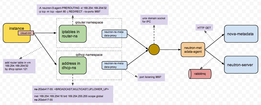
http://niusmallnan.github.io/_build/html/_templates/openstack/metadata_server.html
另外推荐孔令贤的blog
【OpenStack】metadata在OpenStack中的使用(一)
【OpenStack】metadata在OpenStack中的使用(二)
步骤40:通过VNC可以看到启动过程
VNC是一个很好的东西,尤其是在VM没有得到IP的时候,你可以通过VNC连进去,用用户名密码登陆,然后调试为什么DHCP失败。
VNC也是比较复杂的东西,推荐文章

步骤41:添加一个FLoating IP,可以通过Floating IP SSH进去。
要想Floating IP成功,除了IPTables NAT要正确,br-ex也需要正确配置。

步骤42:在VM里面可以访问外网
要做到这一点,除了gateway要配置正确,dns server也需要正确配置。
如果虚拟机网络有问题,那是很头疼的时候,建议通过下面的流程进行调试:
Security Group全部打开,这是最基本的,但是很多人容易忘记,结果tcpdump了半天,发现security group没打开,真的很冤
通过界面查看虚拟机的log,也可以在compute节点上查看console.log文件,看看里面是否有DHCP获取IP成功的日志,如果有,还不错,如果没有就惨了
如果虚拟机连不上DHCP Server,则需要准备一个不使用metadata server,而是用用户名密码可以登录的image,通过VNC登录进去,如果VNC也不通,就需要先调试VNC,这是访问虚拟机最后的方法了。
通过VNC登录进去后,就可以通过命令行运行dhclient,来重启连接DHCP Server
在运行dhclient之前,需要通过ovs-vsctl show和brctl来查看,各个网卡和bridge之间关系是否正确,tunnel之间是否能够通,网卡是否都处于up的状态
如果从虚拟机的虚拟网卡到DHCP Server的网卡一路都是正确的,则需要查看br-tun上ovs-ofctl dumpflows查看flows规则,是否对包的改写正确,是否有正确的规则
可以再dhclient运行的时候,从compute节点上的网卡和bridge,一个个进行tcpdump,看到底哪个网卡或者bridge没有收到包,收到的包里面的VLAN ID等是否正确,问题往往就是这里
如果VM能从DHCP Server获得IP,则好事成了一半,接下来换一个有cloud-init的image,看metadata server能够连接成功,能够注入key,也是通过console.log来看
如果metadata server不能连接成功,就需要顺着metadata server的整个流程,一个一个模块看,看每个模块的log,端口是否正确,是否收到请求,也可以在VM里面用curl来模拟metadata server的请求
如果metadata server能够连接成功,key成功注入,下一步需要从namespace里面看是否能够ping通,能够ssh
如果namespace里面能够成功,则在network节点上,ping floating ip和ssh,是否能够成功,如果不成功,看br-ex的网卡是否添加正确,是否配置了ip,路由表是否正确,namespace里面floating ip的iptables规则是否添加正确
在network节点上能够ssh到floating ip,则需要从其他节点上ssh,如果不成功,可能br-ex的网址配置有问题,很可能是br-ex添加的物理网卡不是混合状态,也可能是路由配置有问题,对于floating ip所在的网段,不指向network节点
如果floating ip能够成功,则需要进去VM里面运行apt-get update,如果不可以,看能否ping通openstack里面的gateway,然后看能否ping通物理网络环境的gateway
最后要看DNS Server是否配置正确,是否能够ping通,如果能,apt-get update运行成功,则虚拟机才叫基本可用。
所谓基本可用,就是能运行简单的命令没有问题,但是,如果想里面运行程序,则需要保证kvm的性能
推荐文章http://www-01.ibm.com/support/knowledgecenter/linuxonibm/liaat/liaatkvm.htm
而且虚拟机之间是共享物理机的资源的,我们必须对虚拟机的QoS进行控制,可用通过cgroup来进行控制
推荐文章
[转] Quality Of Service In OpenStack
虚拟机在一个物理机上运行,当资源紧张的时候,可能需要live migration到另外的机器上
QEMU KVM Libvirt(12): Live Migration
九、Cinder

虚拟机创建完毕,我们常会attach一个volume,当然也可以boot from volume,这样volume里面的数据不会随着VM的消失而消失。
步骤44:Cinder API请求创建一个Volume
步骤45: Cinder Scheduler在多个Cinder Volume里面选择一个,也是先Filter再weighting的过程,可以根据总空间的大小,也可以根据分配的情况
步骤46:Cinder Volume创建一个iscsi target
步骤47:Cinder Volume创建一个LVM volume,加入iscsi target
步骤48:compute节点连接iscsi target,从而volume出现在compute节点上
步骤49:将compute节点上的volume attach到虚拟机上
对于Cinder
Cinder架构

对于LVM,推荐文章
[转] Linux 内核中的 Device Mapper 机制
http://www.ibm.com/developerworks/cn/linux/l-devmapper/


对于ISCSI
推荐
Using iSCSI On Ubuntu 10.04 (Initiator And Target)
Linux tgtadm: Setup iSCSI Target ( SAN )


Cinder跟其他的存储

